The fully housed mortise and tenon joint represents a fundamental connection in timber framing that combines the mechanical strength of traditional mortise and tenon joinery with enhanced load-bearing capacity through housing. This joint type creates a dual load path: the tenon provides lateral resistance and alignment, while the housing directly transfers vertical loads from beam to post, significantly increasing the joint's structural performance.
Housing refers to the deliberate removal of material from the receiving timber (typically a post) to create a bearing surface that accepts the full cross-section of the incoming member. This technique serves multiple structural and practical purposes: it increases the effective bearing area, helps resist twisting and checking of the housed member, conceals gaps that may develop as timbers season, and provides a more refined aesthetic appearance.
The depth of housing typically ranges from 3/4" to 1-1/2", though actual dimensions should be determined based on load calculations, timber species, and member sizes. As a general guideline, housing depths of 3/4" to 1" are standard for most residential applications, while heavier commercial loads may require deeper housings approaching 1-1/2" or more.
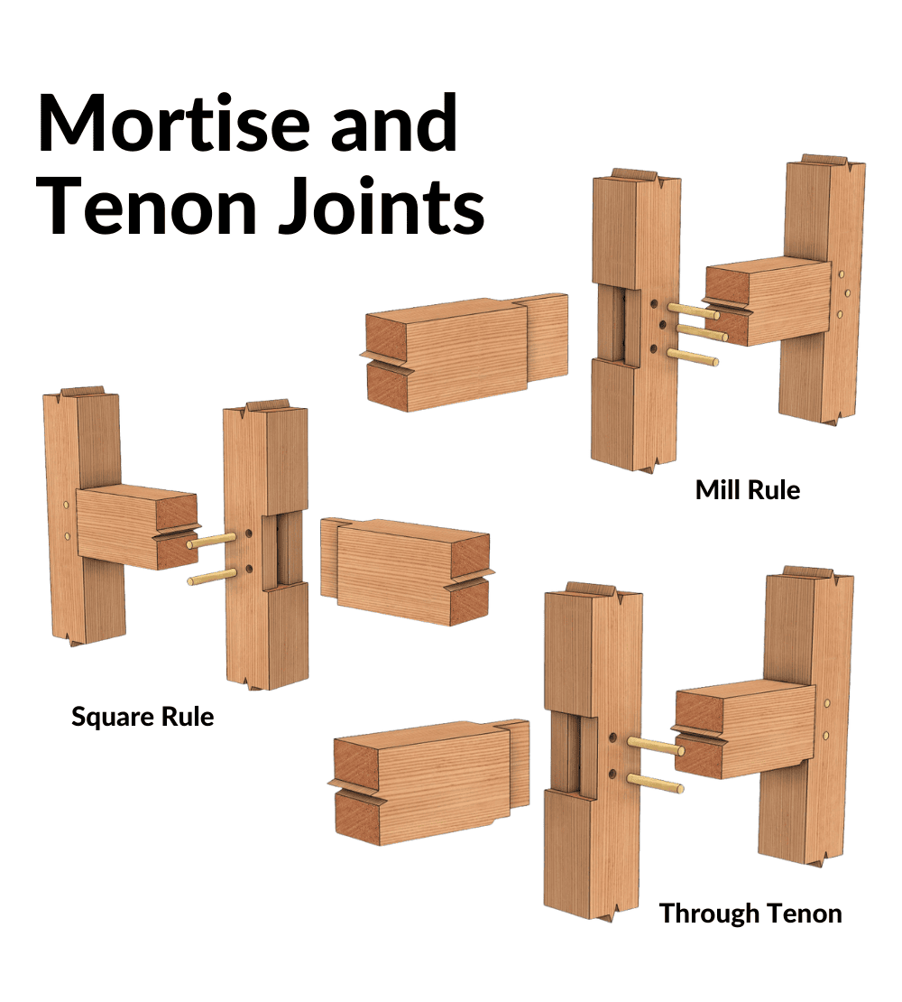
Mill Rule Mortise and Tenon Joint


Historical Development
Mill rule layout emerged around the turn of the 20th century as sawmill technology advanced and precision milling became economically feasible. This method assumes timbers are dimensionally accurate and square, having been processed through a four-sided planer (S4S - surfaced four sides). The term reflects its dependence on mill-produced material rather than hand-worked timber.
Core Methodology
Mill rule represents the most straightforward layout approach in timber framing. It operates on the assumption that all timber faces are square, flat, and true to dimension. Layout proceeds directly from the actual edges of the timber using standard carpentry techniques—measuring with framing squares, marking with the square's tongue for cross-cuts, and laying out mortises and tenons parallel to the outer faces.
Technical Specifications
In mill rule work, what you see is what you get. An 8x8 post is expected to measure 7-1/2" x 7-1/2" (actual dimensions) consistently along its length. Mortises are laid out parallel to the timber faces without reduction or compensation. The precision of modern sawmill equipment means these timbers typically maintain tolerances of ±1/16" or better.
Housing in Mill Rule Applications
When housing is incorporated into mill rule joints, it serves primarily to increase bearing capacity rather than to compensate for dimensional irregularities. Housing depths are precisely controlled and consistent across the joint face. Because the timbers are already square and true, housings cut to a specified depth will be uniform across the entire bearing surface.
The decision to house a mill rule joint depends on load requirements rather than layout necessity. With surfaced S4S material creating perfectly square shoulders, some applications may not require housing at all—the tenon shoulders can provide adequate bearing.
CNC Integration
Mill rule layout is ideally suited for CNC (Computer Numerical Control) machining. The assumption of perfect timber geometry aligns precisely with CNC capabilities, allowing complex joinery to be cut with exceptional accuracy. Features like four-shouldered tenons, intricate decorative elements, and compound angles become practical when machine-cut on milled stock.
Square Rule Mortise and Tenon Joint


Historical Context and Development
Square rule layout emerged in early 19th century America as a systematic approach to timber framing that could accommodate the irregular, rough-sawn timbers common to the period. The term "Square Rule" was coined by Edward Shaw in his 1830s publication "Civil Architecture" to describe this traditional system. Unlike older European scribe rule methods that custom-fitted each joint, square rule established a standardized approach that revolutionized American timber framing.
Fundamental Principles
The square rule method operates on the premise that within every irregular timber lies a smaller, geometrically perfect timber. This conceptual "inner timber" serves as the reference for all joinery layout and cutting. For example, a rough-sawn 8x8 post that actually measures 8-1/4" x 7-3/4" would be laid out as if it were a perfect 7-1/2" x 7-1/2" post, with all joinery referenced to this reduced dimension.
Layout Process
The layout begins by selecting two adjacent reference faces on each timber—typically the squarest or most consistent faces. From a reference corner (called the arris), the framer measures inward by a predetermined distance (commonly 1/4" to 1/2" per face) to establish the theoretical boundaries of the inner timber. These reference lines are marked at both ends and connected with chalk lines snapped along all four faces, creating a consistent geometric framework for layout.
All mortises, tenons, and housings are then laid out parallel to these reference lines rather than to the actual timber faces. This allows the framer to work with consistent, predictable dimensions despite variations in the timber's actual cross-section.
Housing Characteristics in Square Rule
Housings in square rule work are cut parallel to the layout lines and reduce the rough oversize timber to the nominal dimension at the joint location. The housing depth is measured from the reference line inward, maintaining consistency regardless of the timber's actual surface profile. This parallel reduction approach means that housings on rough-sawn timbers may appear deeper on one side than the other, but structurally they provide uniform bearing at the nominal dimension.
Structural Advantages
Square rule fully housed joints excel with rough-sawn or hand-hewn timbers where dimensional consistency cannot be guaranteed. The system accommodates timber variation while maintaining structural integrity through standardized bearing surfaces. The housing provides full bearing at the reduced dimension, ensuring predictable load transfer even as timbers season and potentially move.
Technical Considerations
When engineering square rule joints, calculations should be based on the reduced nominal dimensions rather than actual timber sizes. The housing effectively creates a uniform bearing surface at the reference dimension, which is what carries the load. Peg placement should be referenced from the housing shoulder, typically starting 2" from the bearing surface and spaced at minimum 3.5 peg diameters center-to-center.
For joints subjected to green timber shrinkage, pegs should be positioned (justified) toward gravity. This means placing them toward the bottom of horizontal members, allowing the beam to shrink while maintaining contact with the housing seat. Drawing pegs 1/16" for hardwoods and 1/8" for softwoods helps maintain joint tightness.
Through Tenon Mortise and Tenon Joint


Definition and Structural Function
A through tenon, also called a "through mortise and tenon" or "thru tenon," is a joinery technique where the tenon extends completely through the mortised member, emerging visible on the opposite face. This represents one of the most robust connection methods in timber framing, providing exceptional resistance to tensile forces while offering opportunities for both structural enhancement and aesthetic expression.
Mechanical Advantages
The through tenon creates superior structural performance through several mechanisms:
- Full Wood-to-Wood Contact: The tenon's passage through the entire post thickness maximizes the gluing or friction surface area, distributing loads across the maximum possible interface.
- Enhanced Peg Effectiveness: Pegs driven through a through tenon can be positioned to engage wood on both sides of the mortise, creating a more effective mechanical lock. The protruding tenon allows pegs to be drawn completely through the joint, ensuring full engagement.
- Wedging Capability: Through tenons permit wedging from the exterior face, allowing the joint to be drawn tight and locked mechanically. Wedges driven into kerfs cut in the tenon end expand the tenon, creating a dovetail-like mechanical lock that resists withdrawal.
- Self-Tightening Behavior: As timber seasons and shrinks across its width, properly wedged through tenons can maintain or even increase their grip within the mortise, unlike blind tenons which may loosen with shrinkage.
- Visual Inspection: The visible tenon end allows for ongoing assessment of joint condition, making maintenance and structural evaluation more straightforward.
Tenon Proportions: Through tenon thickness typically follows the standard rule of approximately 25-33% of the beam's nominal width. However, for a through tenon subjected to wedging, consider:
- Minimum thickness of 1-1/2" for adequate wedge kerfs
- Tenon height proportional to beam depth (typically 50-75% of beam height)
- Adequate relish (material beyond peg holes) of 3" minimum
- Shoulder depth of 2" minimum for proper bearing
Mortise Depth: The mortise must extend completely through the post. Over-boring by 1/4" beyond the back face helps prevent blowout during drilling and provides clearance for tenon insertion. Post thickness determines minimum mortise depth, typically 5-1/2" to 11-1/2" depending on post size.
Housing Integration
When combining through tenon joinery with housing, the housing depth must be carefully coordinated with the through tenon geometry. Typical configurations include:
- Full Housing with Through Tenon: The housing extends across the full beam width, providing complete bearing surface. The through tenon passes through the center of the housed area. This provides maximum load transfer and the cleanest appearance.
- Partial Housing: Housing is cut only to the depth necessary for structural requirements (typically 3/4" to 1-1/2"), with the tenon mortise cutting through the housing floor. This conserves material in the post while maintaining adequate bearing.
Historical Context and Modern Practice
Evolution of Housed Joinery
Fully housed mortise and tenon joints represent an evolution in timber framing that balanced the structural advantages of direct bearing with the practical reality of working with less-than-perfect timber. Historical evidence suggests housing became more prevalent as American framers developed square rule systems in the early 1800s, using the technique to standardize joints despite timber irregularity.
Earlier scribe rule frames often employed diminished housings (housings that angle rather than remain parallel to joint faces), while square rule heavily relied on parallel housings cut to nominal dimensions. As mill technology improved through the late 19th and early 20th centuries, housing remained valuable even with precision-milled timber because it continued to offer structural benefits—increased bearing area, reduced stress concentrations, and improved long-term performance.
Contemporary Applications
Modern timber framing continues to employ housed joints for several reasons:
Structural Efficiency: Building codes and engineering requirements often demand higher capacity connections than un-housed joints can provide without supplemental hardware. Housing adds capacity without visible steel.
Green Timber Accommodation: Despite kiln-drying availability, many projects utilize green timber for economic or traditional reasons. Housing helps manage the gaps that develop during seasoning.
Aesthetic Preference: The clean, refined appearance of housed joints appeals to clients seeking traditional timber frame character without the rustic appearance of un-housed connections.
CNC Compatibility: Computer-controlled manufacturing makes cutting precise housings efficient and cost-effective, particularly in mill rule applications.
Integration with Modern Building Systems
Contemporary timber frames often integrate with modern building technologies—SIPs (Structural Insulated Panels), conventional wall systems, and engineered floor assemblies. Housed joints facilitate these connections by providing predictable, engineered load paths that building inspectors and engineers can verify against code requirements.
Through tenons, particularly when combined with housing, provide exceptional performance in hybrid buildings where the timber frame must resist both gravity loads and lateral forces from wind or seismic activity. The ability to calculate and document joint capacity makes housed through tenons particularly valuable in commercial applications where engineering documentation is required.
Engineering Resources and Standards
Timber frame joint capacity and design should reference:
- National Design Specification (NDS) for Wood Construction - Published by American Wood Council; provides allowable stress values and connection design methods
- International Building Code (IBC) - Current edition specifying structural requirements
- Timber Frame Engineering Council (TFEC) - Professional organization publishing technical bulletins and research on timber frame connections
- Timber Framers Guild - Professional association maintaining technical library of research papers on joint performance
Engineers should specify tested and documented species values, consider load duration factors, and apply appropriate safety factors per code requirements. When standard calculation methods are insufficient for complex joints, finite element analysis or physical testing may be warranted.
Conclusion
Fully housed mortise and tenon joints, whether executed in square rule, mill rule, or through tenon configurations, represent a sophisticated joining system that balances structural performance, practical fabrication, and aesthetic appeal. Understanding the distinct characteristics of each approach allows framers and engineers to select the optimal method for specific project requirements.
Square rule accommodates rough-sawn timber variability while maintaining predictable structural performance through standardized reductions. Mill rule leverages precision milling for speed and accuracy in modern production environments. Through tenons provide maximum strength and visual character where tensile resistance and traditional aesthetics are priorities.
All three approaches benefit from the structural advantages of housing—increased bearing area, improved load distribution, and enhanced long-term performance. As timber framing continues to evolve, integrating traditional joinery wisdom with modern engineering analysis and CNC precision, fully housed mortise and tenon joints remain fundamental to creating strong, beautiful, and enduring timber structures.
General Technical Specifications for Housed Joints
Standard Dimensions and Proportions
Housing Depth:
- Light residential loads: 3/4" to 1"
- Standard residential: 1" to 1-1/4"
- Heavy timber or commercial: 1-1/4" to 1-1/2"
- Exceptional loads: Engineered depth per structural calculations
Tenon Thickness:
- 4x and 6x beams: 1-1/2" (minimum practical for tooling)
- 8x beams: 2"
- 10x and larger: 2-1/2" to 3"
- General rule: 25% to 33% of nominal beam width
Mortise Depth:
- Blind mortises: Tenon length + 1/4" clearance
- Through mortises: Full post thickness + 1/4" over-bore
Tenon Length:
- Blind tenons: Post width - housing depth - 1/4" minimum clearance
- Through tenons: Full post thickness + 1/4" to 1/2" proud
Peg Specifications:
- Diameter: 3/4" to 1" typical (1" most common for 8x+ timbers)
- Material: Seasoned hardwood (oak, locust, maple)
- Spacing: 3.5x diameter minimum center-to-center
- Edge distance: 2" from bearing surface minimum
- Draw bore offset: 1/16" hardwoods, 1/8" softwoods
Load Transfer and Engineering
Bearing Stress Calculation:Bearing stress = Applied Load / (Housing Width × Housing Depth)
For a 8x10 beam housed 1" into an 8x8 post:Bearing area = 7.5" × 1" = 7.5 square inches
If compression perpendicular to grain (Fc⊥) for species = 625 psi:Allowable load = 7.5 sq in × 625 psi = 4,688 lbs
Tenon Shear Calculation:Shear stress = Lateral Force / (Tenon Thickness × Tenon Height)
For a 2" thick × 6" tall tenon:Shear area = 2" × 6" = 12 square inches
If parallel-to-grain shear (Fv) for species = 120 psi:Allowable shear = 12 sq in × 120 psi = 1,440 lbs
Combined Loading:Joints typically experience combined vertical and lateral loading. Engineering analysis should consider:
- Bearing stress from vertical loads
- Shear stress in tenon from lateral loads
- Bending in beam cantilever (if present)
- Peg capacity as backup load path
- Interaction equations for combined stresses
Material Selection and Moisture Considerations
Species Suitability:
- Excellent: White oak, red oak, Douglas fir, southern yellow pine, black locust
- Good: Eastern white pine, western red cedar, hem-fir, spruce
- Fair: Poplar, basswood (limited to light loads)
Moisture Content Guidelines:
- Green framing (field assembly): 20%+ acceptable; design for seasoning
- Controlled drying: 15-19% for exterior applications
- Interior kiln-dried: 12-15% for climate-controlled spaces
Seasoning Effects:Green timber frames will experience dimensional changes as they dry:
- Radial/tangential shrinkage: 4-8% depending on species
- Negligible longitudinal shrinkage (< 0.1%)
To maintain housed joint integrity with green timber:
- Position pegs toward gravity (bottom of beams)
- Use draw boring to pre-tension joint
- Accept that gaps will develop (housing minimizes visibility)
- Design housing depth for load after shrinkage
Fabrication Techniques
Power Tool Methods:
- Chain mortiser: Fast, clean mortise walls; requires practice for accuracy
- Drill and chisel: Bore bulk waste with drill guide; clean with timber framing chisels
- Router with templates: Excellent for housings; requires jigs for deep mortises
- CNC machine: Ultimate precision for mill rule timbers; requires CAD/CAM programming
Hand Tool Methods:
- Timber framing chisel: Essential for cleanup and final fitting
- Timber saw: Cross-cutting shoulders; tenon cheek cuts
- Slick: Large chisel for rapid material removal
- Framing square: Layout and squareness verification
Quality Control:
- Check mortise walls for square and plumb
- Ensure mortise depth is consistent
- Verify tenon thickness is uniform
- Test fit joint before final assembly
- Confirm housing provides full bearing
- Measure peg hole alignment before drilling
Assembly and Installation
Sequence for Housed Joints:
- Verify all components fit correctly
- Apply finish (if any) before assembly
- Orient timbers for proper grain exposure
- Insert tenon into mortise
- Drive joint tight with timber framing beetle
- Install pegs using draw bore technique
- Drive wedges (if through tenon)
- Trim pegs and wedges flush (or proud as designed)
Draw Boring Technique:Draw boring creates compression in joints by offsetting peg holes in tenon versus mortise by 1/16" to 1/8". When the peg is driven, it pulls the tenon deeper into the mortise, tightening the joint. This technique is particularly effective with housed joints as it maintains bearing pressure on the housing surface.
Common Issues and Solutions:
- Mortise too tight: Pare with sharp chisel; avoid excessive removal
- Tenon too loose: Shim with wood veneer; recut joint if severely oversized
- Housing uneven: Re-rout or chisel to consistent depth
- Peg won't drive: Chamfer peg end; check hole alignment; verify diameter
- Joint won't close: Check for debris; verify dimensions; look for interfering shoulders
Updated 1-8-2026
Brice,
Why is the mortise slightly off center?
Thanks,
Aaron
It is sometimes easier to offset all the mortises on a frame a certain distance from the reference face, in this case, it is 2 1/2″. It can help minimize errors.
Is there a certain rule of thumb for mortise depth should it be a little deeper than the length of the tenon for expansion and contraction or the same size as the tenon?
Does it change between green timbers and dry timbers?
Thanks
Brit
I shoot for .25 inches as a rule of thumb. No change between green and dry timbers.
Is there a rule of thumb for the depth of the beam into the post? Here it is 3/4″ across the face of the beam into the post. I am using this joint on a 10×10 post with a 6×12 beam going into the post, housed on one side. If I go into the post 1-1/2″ that will keep the bearing happy to meet “code”, since the tenon can not be seen and inspector has to follow the book. But I am not sure if 1-1/2″ is too deep for the post.
No, it is not too deep. The typical housing is .75 to 1″ but it all depends on the loads.
We are framing with green wood. I understand that the mortise and tenon will shrink similarly across the radial plane, but it will be quite different across the height of the housing.
( I see that a 12” thick beam could shrink 3/8 or more, but it’s corresponding housing will shrink only .012”)
Won’t the resulting gap negate the strength advantage of the housing? What are these joints going to look like in five years? Will the load be resting on the shoulder or the housing or on the pegs? Just trying to get the math part of my head around this problem
If you lower the pegs and skew them toward the bottom of the beam that will hold it lower in the mortise as it dries. That will help keep it bearing on the mortise.