There are four layout rules, or systems, in timber framing today. Within those, there are countless combinations in-between. These layout systems are used when you are laying out or marking the joinery on your timbers before cutting them. There are pros and cons to each system.
Scribe Rule
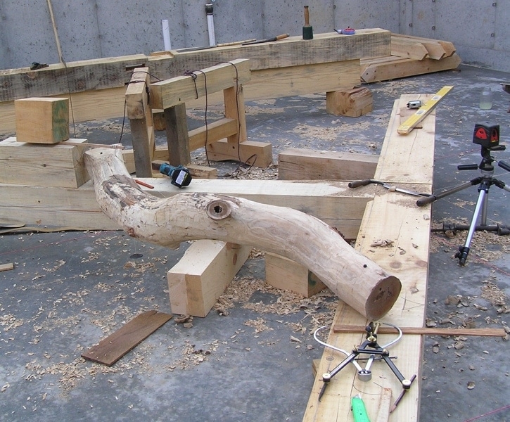
Scribe rule is the most difficult to master, but once you see how it works and can visualize what is happening, it is an incredibly powerful method. This method is ideal if you have organic, out of square, twisted or bowed timbers. You can take care of all of them with this technique. The timbers are stacked on top of each other where they will be located in the frame. String lines, plumb bobs, bubble scribes, and laser lines are used to locate cut marks.
Pros
- You can easily take care of irregular, round, and organic timbers
- It is one of the most rewarding methods to use
Cons
- Takes the most skill and time to master
- More material handling than the other methods
- Timbers are not interchangeable
Mill Rule
 The timbers are cut and planed with a four-sided, larger planer, by a sawyer or yourself, hence the name “Mill Rule”. The material is square, flat, and straight, and will only need sanding to finish it. With the material being so close to dimension, no square rule compensation or scribing is needed. It is just a matter of pulling the dimensions and marking your timbers. The planing process usually takes 1/4” off each side so an 8×8 will be cut to 7.5”x7.5”.
Pros
- It cuts down on time during the layout and cutting process. Sometimes it will offset the costs of itself if you are paying someone to cut your frame.
- All the timbers are constant, and therefore can be interchangeable. Knee braces are the best example.
Cons
- It isn’t a flexible system if you have out of square or rough-cut wood.
- It does have an added cost of the planning and transportation, which isn’t the best for someone who is cutting their own timbers.
Mapping
With mapping, you take detailed measurements of the different pieces and layout the joinery to match them. You must employ some logic and care with this technique. For example, to have the dimensions to lay out a post, you will need to have cut all the preceding timbers, or at least laid them out so you can capture the dimensions where the joinery is located on the timbers.
Pros
- This is a very flexible method that allows you quite a bit of leeway on the sizes of your timbers.
- It mixes well with the other methods.
Cons
- Time-consuming
- Keeping track of all the measurements through a frame can be tricky and can lead to mistakes if not careful.
Square Rule
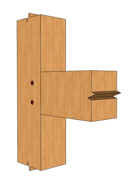
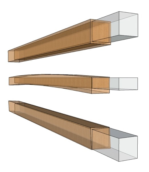
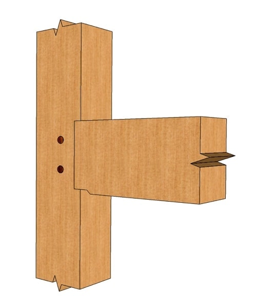 The Square Rule method is predicated on the theory that within each timber, a square and straight timber is sitting there waiting for you. Working with that theory, you can lay out your frame using irregular or rough sawn timbers with a chalk line and a little head scratching. Most of the time when you either cut or purchase rough sawn material it doesn’t come as ordered. An 8×8 post could end up being 7 ⅞” x 8 ⅛” but within that timber lies perfect 7 ¾” x 7 ¾” timber ready for you to cut. You are notching the timbers to standard dimensions to aid in having unified measurements throughout the frame.
For example, you will notch all the 8×10 beams to 9 ½”.
Pros
- You can deal with a lot of variations in timber sizes and account for any twisting or bowing in the timber by using a chalk line
- Allows you to standardize dimensions, which speeds up the layout process
Cons
- Time-consuming to layout and cut all the haunches, housing, and shoulders.
You should introduce first the reference systems these rules can be used with, ie face-reference or line-reference (typically centre line). A square rule used with a face-reference method won’t allow you to deal properly with, say, a severely crowned/bowed beam (the local layout planes on the reference face change orientations along the beam, so if you were to cut mortises at the bottom of the beam they wouldn’t seat flat on the posts); whereas a square rule used with a centerline reference method would fix that.
I was thinking that starting with an overview of the different methods would be helpful for future reference. The next couple of articles I write are going to be delving into the different methods and in those was going to look at reference faces and how they pertain to each one. Stay tuned and thanks for your thoughts!
Where does snap line fit into this, in your experience? I feel like it’s really its own layout system. We commonly use it in conjunction with mapping to get scribe like fits without scribe like material handling.
Hi Brice,
In the Mill Rule, you put that by taking off 1/2″ off the sides of an 8 x 8, that you’d end up with a 7.5 x 7.5.
You’d actually end up with a 7 x 7.
Great article! I really enjoy your content.
I debated about having it as its own method but since it is used in both square rule and the scribe rule it seemed more like a technique/method. I do have an article slated to look at just using snap lines because they are just so handy.
Thanks for the comment and the correction!
Hi Brice
Dealing with out of square timbers, using a level to find horizontal plane measure center line and mark. Then by using a framing square or plumb bob to find plumb line in center of timber and snapping lines around the timber. By pulling measurements of the center lines is this considered line rule,
will this produce square joints
He actually wrote, “taking 1/4″ off the sides” not 1/2″. In which case, you would end up with 7.5 by 7.5
I find that method is a blend of scribe and square rule but I think the term Line Rule, it that what you use?
Awesome. Thanks!
Hey Brice,
I would be interested in the article you mention in this post…is it possible to tell me where to find it? I have a lot of beams that I sawed up myself and I am no sawyer:) So you can imagine how they look for a first timer. I know I am going to have to use a mix of square and scribe but I thought the mix was snap line… Don’t beat me up to much for my ignorance.
Hi Brice
Great start off on this topic. I would love to read more about each rule possibly with some visual aids. I find myself frequenting this site more and more as I plan my pandemic timber frame project. Currently I’m still in the bush harvesting trees.
Cheers
Ab Canada
Which article are you referring to? A mix of the different types of methods is the way most folks go.
Will Beemer’s book, learn to Timberframe has an excellent description of Square Rule.
The Forestry Forum has posts that get into details of the various systems.
Brice your tease for future articles has me waiting for more enjoyable reading.
Thank you!
Beemer’s books is great resource!
I find the line rule / layout method to be a very useful but I feel most people (including myself when I first started looking into it) only understood a few of the puzzle pieces of information needed to truly make this method work without a lot of cussing and pulling of hair. I’m getting ready to build a few timber frames, a small workshop/well house, then a relatively large barn/shop, then finally my house. I “believe” I completely understand the line rule / layout method but I still have one sticking point… Although the joinery within each timber will be square (and plumb) to all the other joints within it’s own timber (and hopefully all the other joints within the frame as a whole), that would still leave the glaring problem with whatever you are attaching to the outside surface, such as siding, cladding, floors, roofs, etc. to not lay flat against the entire surface of the timber they are being laid upon. I feel this method would be great, due to its simplicity, for say entire barns, workshops, roundwood timber framing, and even in a more refined frame for members such as cross-tie beams (that don’t have flooring on top), collar ties and wind/knee braces, since they don’t have have the issue of attaching a long and flat member that will be laid across multiple members cut with the line rule / layout method… but if you plan on say putting flooring down on top of a bunch of floor joists cut with this method or hanging clapboard siding against the posts, wouldn’t they be only coming into contact with the proudest corner? What am I missing? I mean a floor joist wouldn’t even sit flush with the beam it is pocketed into nor would a girt be flush with the posts. I guess you could plane one surface flat (that would have the cladding/decking attached) and begin laying out your timber from there, that could work but not for members such as sill beams which would need both the bottom and outer surface to be square to each other. Just trying to nail this down before I figure it out halfway through the frame. Thanks in advance for anyones experienced prospective.
You are correct in your thinking and it can lead to problems. The solution that I have uses it to plane those surfaces flat to the surface you are using.
There are only two reference methods and therefore rules; center and face. Try making a shirt using face reference and it will look like a bag. Irregular forms like humans and logs require a center reference. Machined logs, timbers and lumber can be face referenced but that’s an expensive process. Milling and Scribing are just processes and do not deserve the authority of a reference Rule. What you’re missing is Center Rule, first introduced in the West as Axis Mundi (Earth Axis) during the ancient Roman Empire. Still practised today throughout the Orient, called the Middle Path (centreline) following the ancient Chinese Yingzao Fashi, book of building standards printed in 1103. Center Rule and it’s four construction forms/methods is what my books are all about, coming out his summer /24: Log Building, A Masters Guide and Timber Framing, A Masters Guide by James D. Mitchell
Thanks for your input James. Will be on the look out for the book.
For barns, cabins, and outbuildings, I layout using the outside face off all timbers as the reference point. That keeps the outside faces flush for application of siding/sheathing. I don’t mind having the extra dimension fall out on the inside or underside of the timbers. If you’re going to use those inner/underside surfaces to install a finish, then that’s a different story.
Thank you for your input
Thanks for the good explanation.
You forget the oldest layout method in the world, Center Rule, also known during Roman Empire as Axis Mundi, and in ancient Chinese Yinzao Fashi.
Truly there are only two reference systems, centreline for irregular objects and face uniform objects. For in-depth explanation refer to James Mitchells companion books LOG BUILDING, A Masters Guide and TIMBER FRAMING, A Masters Guide. Available July 1, 2025
Thank you for your input!
You are missing the oldest and most used method in the history of big wood log and timber construction… Center Rule.
During the ancient Roman Empire timber post and beam (Opus Craticum) was the vernacular with the Centreline (Axis Mundi) as reference to measure from/to and for orientation.
In ancient China the Yinzao Fashi (Book of Standards printed 1103) used Center reference (Middle Path) for all construction.
Refer to James Mitchell’s new companion books on big wood Center Rule: LOG BUILDING, A Masters Guide and TIMBER FRAMING, A Masters Guide.
You’re absolutely right—Center Rule has a long and foundational history in timber and log construction. The examples you shared, from Opus Craticum in Roman times to the Yingzao Fashi in China, are a great reminder of how deeply rooted the practice is across cultures. While it’s always valuable to learn from these traditions, our article focuses on more modern techniques to give clients clear, practical references. Since most projects today don’t involve cutting fully rounded or irregular timbers—the original context where Center Rule was essential—we highlighted methods more commonly applied in contemporary work.