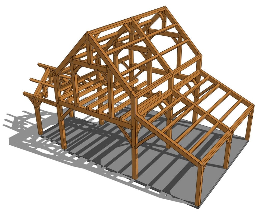
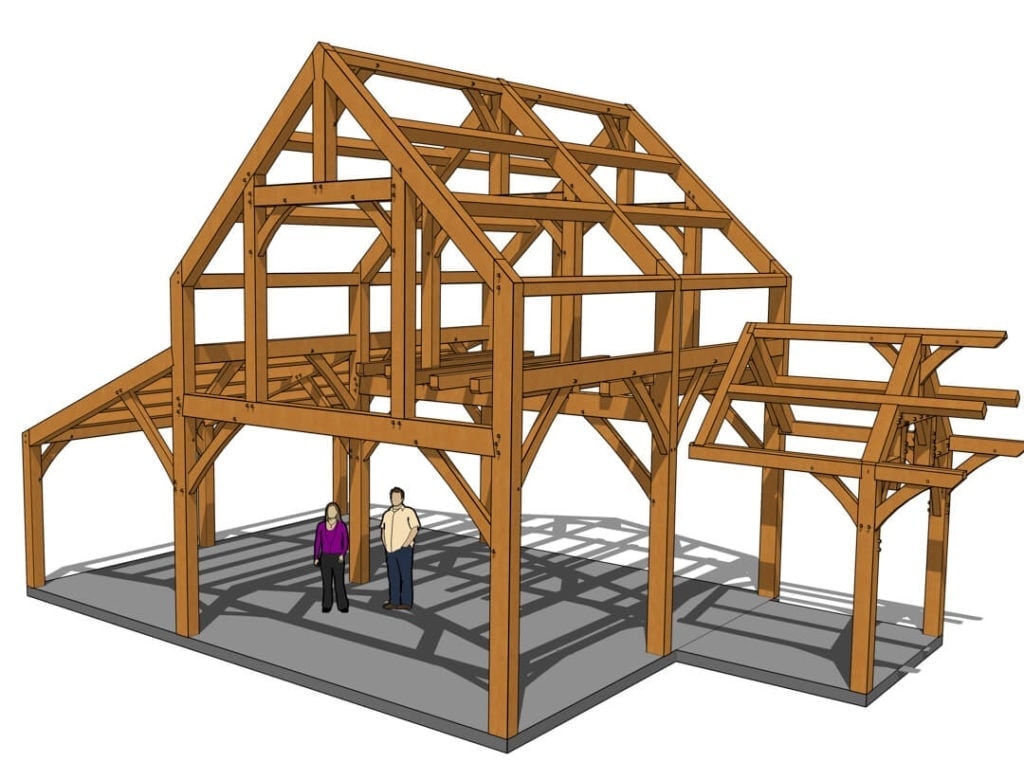
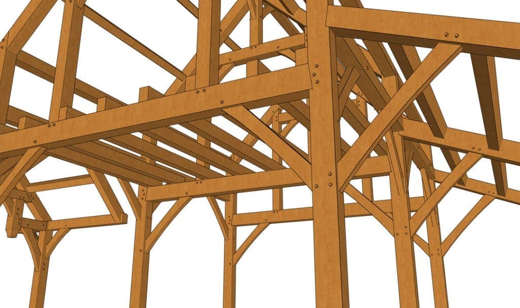
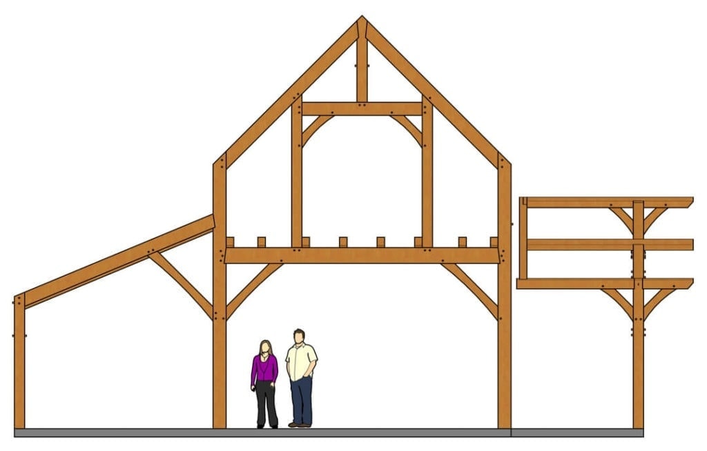
Bold Architecture. Expansive Living. Lasting Craftsmanship.
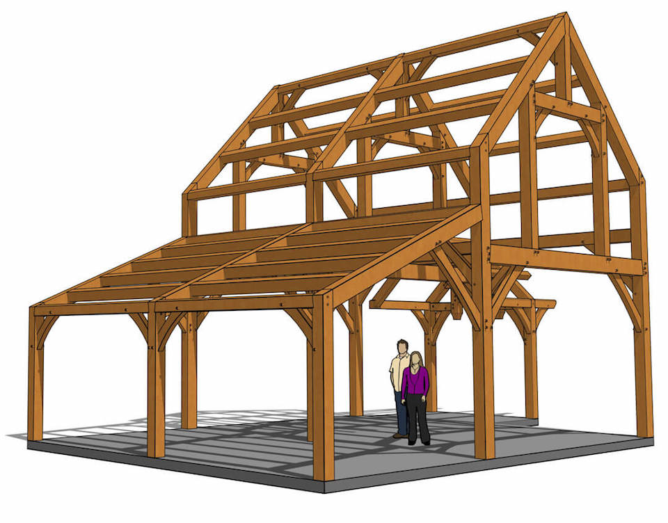
The 24x30 Timber Frame Cabin is more than just a build—it’s a showstopper. With nearly 1,000 square feet of architectural charm, this two-level timber frame brings together soaring ceilings, handcrafted timber features, and flexible space in one unforgettable design.
Floor Plan Highlights:
- Main Level: 956 sq ft of open, airy living space
- Optional Enclosed Porch: Adds 80 sq ft for a total of 1,036 sq ft
- Upper Level: Features 5' knee walls and 9' ceiling height at the ridge for generous headroom
- Loft Detail: Central loft section cantilevers 3 feet out for dramatic sightlines to below
- Entry Design: Hammer-beam truss and extended purlins set the tone with stunning curb appeal
From the outside in, every inch of this frame is packed with detail. The soaring tie beams top out at nearly 11 feet, and the lean-to wing’s roofline lifts from 8 feet at the eaves to 13 feet at the peak, filling every space with light and volume.
Large queen post trusses on the gable ends allow expansive windows, while clerestory options in the knee walls and minimal post requirements on the lower level give you the creative freedom to let in the views from every angle.
Buy This Plan
This plan provides detailed, easy-to-follow blueprints, perfect for anyone building their own timber frame.
Customize or Kit
Do you like this plan but need to change it a little, or do you want a complete Ready-To-Raise Kit?
Download Brochure
Like this plan? Want a little more information? Access our downloadable PDF.
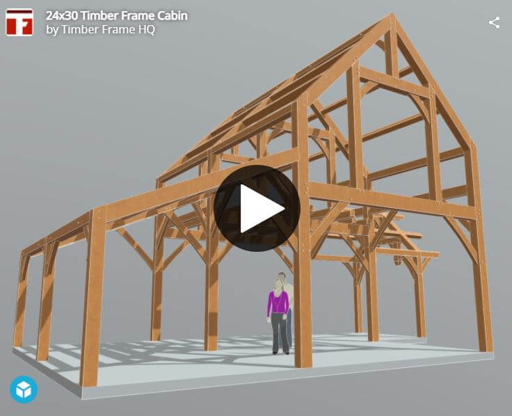
View Our Interactive 3d Model
We understand that every project is unique, so we offer extensive customization options for our plans and kits. Choose from various sizes, roof styles, and finishes to match your style and landscape. Our design team is dedicated to helping you create the perfect plan that reflects your vision.
Here's How You Can Get Started:
- Phone: Call us at 888-552-9379 (9–5, M–F) to speak with one of our experts.
- Email: Send your questions to projects@timberframehq.com, and we will respond within two business days
- Online Form: Please complete the form below, and we will respond promptly.
Get An Instant Quote
Use our online calculator to get a quote for a complete Ready-To-Raise™ Kit. Just need your zip code.
The shed roof section of this design should have a strong top plate and rafters running from the top plate to the wall. The current design with beams running between 3 rafters will probably fail if there is a heavy snow load . Snow from the main roof will land on the lower shed roof, especially if a steel roof; the middle beam has to carry it all.
Hi Mike,
The Principal Rafter’s spanning length have been shortened by the braces underneath. That brace has another on the opposite face that is taking some of the deflection of the tie beam from the roof load above. Actually a neat arrangement. Yes the snow does fall off the upper roof. This 50% tributary area that the middle principal rafter carries of the roof (not all of it) has been alleviated by that member being a larger cross section than the End Principal Rafters.
Please forgive what may seem a silly question to those who design & build these structures regularly. How is the cabin wall end of the hammer beam entry supported? The pictures suggest that the entire entry structure is balanced on the two vertical posts. Thanks!
No silly questions. In that scenario, you would prop the beam ends on support built into the exterior wall that encloses the timber frame structure. Or if you didn’t want to penetrate any sheathing on the enclosure wall, pack the wall with studs at the area and fasten a corbel to the sheathed wall to hold up the beam. Good anchorage would be required.
Thanks a bunch for the clarification. I can see where this provides for artistic creativity, if one is inclined. I appreciate that!
Now, what’s up with this site requiring me to create an account to purchase these plans?
MJA
Can you give the system another try, you should only have to create an account if you get the Plan Bundle. Let us know if you are still having problems.
This plan has no floor. In fact, most – if not all – of the plans in the bundle have no floor! Let’s assume, for a moment, that whoever buys the plans doesn’t intend to build on a concrete slab – what do they do about a floor?
Most folks do build their frames on top of a slab. We can draw floor systems on a custom basis. Check out our custom design services here.
Got it – thanks Katrina!
Hello
Could you please tell me the dimensions of the main structure alone to the outside of the posts(those are 8×8?). I think I want to build it but with three bents, omit the lean to, and build the hammer beam section on the gable end as the vestibule.
Thank you!
The posts are actually 8×10. The main structure measures 18×24 to the outside of the posts.
I really like your plans, especially the hammer beams. I guess overhangs are not authentic design elements but they are so beneficial that I would like to use them for my project.
Jack – Some of our plans have overhangs and some do not. If the frame is designed to have walls such as this one we may omit them. It is not good to have interior timbers stick through the building envelop. To do that would in a heated/cool space would lead to moisture issues. There are ways to take our plans and modify them to add the overhang.
What are the interior dimensions of the top floor, bottom gamble section and shed roof section?
Here is a screenshot of the loft plan
Is the material list for this cabin the same as the heavy timber cabin of the same size
No, there are enough variations that it is not an exact match.
Is the out side walls include in these plans
No, we do not include cladding in the stock plan. We could tailor that, windows, room layouts etc for you through our custom design department!
I’m looking for a barn/ 2 car garage structure with a fill loft. The overall size of this design looks just about right. Will it accommodate 2 garage doors in the main strucutre and can the loft extend further that 1/2 way?
The dimensions in the shed area are 12′-0″ outside to center of the posts, by 8′-0″ high from the subfloor to the top of the shed timber.
What is the size of the main cabin?
The main cabin is 18′ x 24′ outside to outside of the posts.
My wife and I have built two timber frames from your plans, they have been good to work from. Within the next couple years we are wanting to do a timber frame addition onto our house, I have been eyeballing this plan but would want to add another bay which is fairly easy to do, but I would also like to convert two of the(open, no loft) main bays to a Hammer beam design, it looks like it would lend itself well to this, what are your thoughts on that idea?
Sean, that would be a great plan for that! Would not be hard to modify the plans for this, but let us know if you need any help with the customization! Would love to see some pictures of your other projects.